3. Working with Modules
While in theory you could create your entire design as a single flat
collection of primitive gates, when a design gets too large it becomes
too difficult to manage this way. In order to manage the complexity
of a large design, we must use hierarchical design practices. As with
most other tools, TkGate uses modules to manage this complexity.
Modules serve a similar purpose as functions do in a C program. They
allow the design to be broken into manageable chunks as well as allow
for reuse.
3.1 Module Implementations versus Module Instances
TkGate distinguishes between "Modules Implementations" and "Module
Instances." A module implementation is analogous to the definition of
a C function. It specifies what the module does, and what its
interface is. This is divided into an internal definition which is
created in an editor window in the same way as any other circuit, and
an interface which specified the ports and properties of those ports
(analogous to the function prototype or parameter list in a C
function).
A module instance is analogous to an invocation of a function in a C
program. It is generally displayed as a box with input and output
wire attached to it. Each instance of a module operates independent
of the other instances. When realized as a circuit, each instance
would take up chip area, and be comprised of its own physical wires
and components. When simulating, TkGate maintains separate state for
the values of wires in each instance and the values of any registers
or memories.
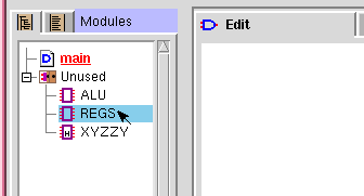
1) Select a module from the module list.
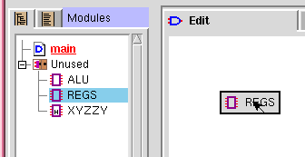
2) Drag to the insertion location.
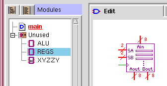
3) Release mouse button to create.
Figure 3.1: Creating a Module Instance
The easiest way to create a module instance is to drag the module name
from the module list. To do this, first 1) select a module from the
module list. In this example, we have selected the "REGS" module.
Next, 2) drag the module name onto the canvas. The module name will
get dragged onto the canvas. Finally, 3) release the mouse button to
create an instance of the module. After you have created the module
instance, you can select it and drag it with the mouse to position it
exactly where you want it.
Another way to create a module instance is to right click and select
"Components → Module → Module Instance" from the pop-up menu, or
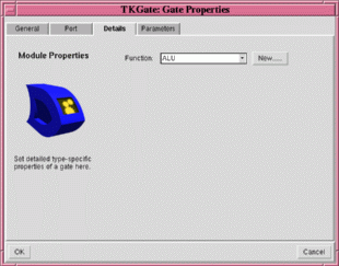
use the "B" keyboard shortcut. When you do this, the "Details" page
of the module properties box will appear to allow you to select which
module you wish to create an instance of. Select a name from the list
box labeled "Function", or press "New..." to create an instance of a
new type of module that you intend to define later. After you have
selected the type of module, press "OK" to create the module instance.
If you press "Cancel", the operation will be aborted and no module
will be created.
When you create a module instance, that instance will have a unique
instance name, distinct from the name of the module type or function.
The instance name allows you to distinguish between different
instances of a module. For example, if you create two REGS modules,
one might have an instance name of "g1" and one might have an instance
name of "g2". Normally, TkGate automatically assigns the instance
name, but you can change it on the "General" tab of the Gate Properties Box dialog box.
Note that this dialog box displays and modifies properties of the
module instance, not the underlying module implementation.
Your design in TkGate is comprised of a hierarchy of module instances.
There is one module that is designated the top-level module. By
default, this module is called "main", but you can rename it to any
module you wish. You can also designate any module in your design to
be the top-level module. Module instances that are directly included
in the top-level module form the next level in the hierarchy, and
modules instances included in those 2nd layer modules form the next
layer and so on.
3.3.1 Module Hierarchy View
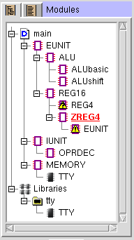
Figure 3.3: Module
Hierarchy View
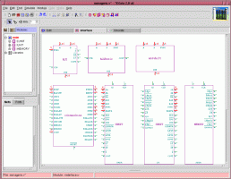
TkGate's module hierarchy view displays the module hierarchy of your
design. Be sure you have selected
to see the hierarchical view. When you are in
edit mode, the hierarchy is shown in terms of module implementations.
That is, at each node in the tree, the children are the names of the
modules which are used as instances at least once in the module.
Consider the example shown to the right. The top-level module "main"
is indicated by the
symbol next to it.
In this example, "main" uses one or more module instances of the
"EUNIT", "IUNIT" and "MEMORY" modules. The "REG16" module uses one or
more instances of the "REG4" and "ZREG4" modules, but the
symbol next to "REG4" tells us that there is no
definition for that module. The module "ZREG4" shown in red with an underline
indicates that that module is the current module in the editor. The
symbol next to "EUNIT" underneath "ZREG4"
indicates a conflict. ZREG4 includes an instance of "EUNIT", but
"ZREG4" itself is contained in an "EUNIT" (it is in "REG16" which is
in "EUNIT"). Circuits containing conflicts can not be simulated, all
conflicts must be resolved before you can simulate.
Each module in the module list or hierarchy view is preceded by a
symbol showing its type. The possible types are:
Symbol | Description |
 | The top-level module. |
 | A normal net-list module. |
 | A text HDL module. |
 | Collection of module libraries. |
 | A module library |
 | A module defined in a library. |
 | Collection of modules defined but not used in the circuit. |
 | Reference to an undefined module in hierarchical list. |
 | Conflict/recursive definition in hierarchical list. |
HDL and net-list modules may also contain a "lock" on them (for
example
). The lock indicates that
editing of that module has been disabled in the module options dialog
box.
Double click on a module in the module hierarchy or module list view
to open that module in the editor. You can also right click on a
module instance in the main editing window and select "
Open". When you use "
Open" to open modules, TkGate will remember
the modules you have opened on a stack. The modules on the stack will
be displayed in red, with an underline under the module currently
displayed in the editor. To close a module, and return to the parent
module on the stack, right click in a blank area on the canvas and
select "
Close".
3.4 Creating and Manipulating Modules
3.4.1 Creating Modules
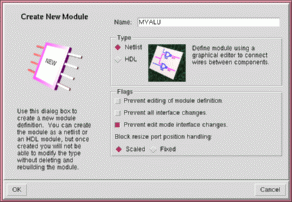
To create a new module, press the
button on the toolbar. This will open the
dialog box shown in Figure 3.4. After you
have opened the dialog box, choose a name for your module and enter it
into the "Name" field. Next, choose a module type. A "netlist"
module is one that is defined graphically by connecting gates and
other modules, and "HDL" module is one that is defined by typing a
text description of the module. You can not change the type once the
module has been created. In order to change the type, you must delete
the module and create a new one of the new type.
There are also several property flags that you can set for your module:
- Prevent editing of module definition: While this property
is set, editing of the definition (inside) of the module is disabled.
However, you can still open the module to view the definition.
- Prevent all interface changes: While this property is set,
editing of the module interface (size of box, position of ports, etc.)
is disabled.
- Prevent edit mode interface changes: While this property is
set, editing of the module interface is disabled in the edit window,
but the interface can still be modified through the interface editor.
- Block resize port position handling: This property controls
how port positions will be handled when you change the size of the box
of a module interface. If you select "scaled" the distance between
ports will grow and shrink proportionally as you expand and contract
the box. If you select "fixed" the position of the ports will remain
constant, and their position will constrain the minimum size of the
box you can use for a module.
3.4.2 Editing Module Properties
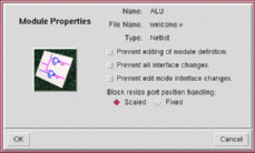
You can edit the property flags of a module by right clicking on the
module name in the module list and selecting "
Properties...". This will bring up a dialog
box like the one shown in Figure 3.5. The
dialog box will show the name of the module, the name of the file from
which that module was loaded, and the type of the module (netlist or
HDL). These properties can not be modified. The modifiable
attributes of modules are the same as those previously described in
Section 3.4.1 Creating Modules.
3.4.3 Deleting, Copying and Renaming Modules
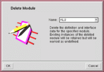
To delete a module implementation, right click on a module in the module list and
select "
Delete". This will
bring up the dialog box shown in Figure 3.6.
Press "OK" to delete the module. You can also change the module to be
deleted by selecting its name from the drop down list. Any instances
of the deleted module used in your design, will not be deleted. If
you attempt to simulate, you will get an undefined module error.
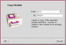
To copy a module implementation, right click on the module to be
copied from the module list and select "
Copy". This will bring up a dialog
box like the one shown in Figure 3.7. Make sure the "From" field shows the
name of the module you wish to copy. Enter the name of the new module
in the "To" field. This will copy both the module definition and the
module interface. The new module will appear in the list, or under
the "Unused" tree in the hierarchy view.
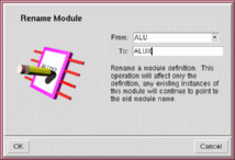
To rename a module implementation, right click on the module to be
copied from the module list and select "
Rename". This will bring up a dialog
box like the one shown in Figure 3.8. Make sure the "From" field shows the
name of the module you wish to copy. Enter the new name for the
module in the "To" field.
3.4.4 Claiming Modules
Sometimes you may wish to modify a module that is part of a library.
But since modules that are part of a library can not be modified, you
must "claim" that module before you can make any changes. Claiming
the module make that module part of your design, rather than part of
the library. This allows you to edit and make changes to the module.
When you save your design, your version of the module will be saved.
Since modules that are defined in your design take precedence over
library modules, the next time you load your design, the claimed
module will continue to be used in lieu of the library version of that
module. If you later decide that you would like to revert to the
library version, you can delete the module, and reload the library.
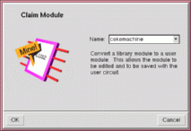
To claim a module, right click on the module to be copied from the
module list and select "
Claim".
This will bring up a dialog box like the one shown in Figure 3.9. Make sure the "Name" field shows the
name of the module you wish to claim. The
symbol next to the module will change to
or
to indicate that that module is now
part of your design.
Only modules that are part of a library can be claimed. If you
attempt to open the claim dialog box when there are no library modules
in your circuit, you will get an error message.
3.4.5 Setting the Top-Level Module
The top-level module is the highest-level module in your hierarchy.
It is the module that appears at the top of the hierarchy view and is
indicated by the
symbol. When simulating
your circuit, only modules that are reachable from the top-level
module are simulated.
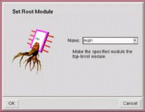
To set the top-level module, right click on the module and select
"
Set As Root". This will bring
up a dialog box like the one shown in Figure
3.10. Make sure the "Name" field shows the name of the correct
module. The module hierarchy view will be recomputed with the new
module as the top-level module.
To edit the definition of a netlist module, open the module as
described in section 3.3.2 Navigating to
Modules. Within the module you can use any of the gates you would
use at a higher level including more module instances. Signals as
passed between the inside and outside through special circuit elements
called ports. There are three types of ports: input, output and
inout. These are shown in Figure 3.11a, b and
c, respectively. Internal module ports are created the same way
as other gates. Right click at the position you wish to create it and
select "Module Input", "Module Output" and "Module InOut" from
"Module" under the "Make" menu. When you are creating a port, the net
properties dialog box will appear to allow you to set the name of the
port. Enter a name, and click OK to create it. The wire connected to
the port will have the same net name as the port.
The ports you define as part of the internal definition of a module
must match the ports that you define on the interface, both in the
names used, the type (input, output or inout), and the bit size. If
you have already created the interface, then you can click on the
"Ports" tab on the lower left-hand side of the main window to see what
ports have been created on the interface.
The interface of a module, is its external appearance when it is
included by a higher-level module. It includes the number and names
of the ports, as well as their position. Each module has a canonical
interface which is stored as part of the module definition when you
save your design. Individual instances of a module have an interface
as well which may or may not match the canonical interface. If you
make changes to the interface of a module after you have created one
or more instances of it in your circuit, you may need to go back and
fix those instances.
While it is possible to edit the interface of a module directly in
edit mode then choose "Interface → Set" to make that instance the
canonical instance, this is not the recommended way of creating
interfaces. The preferred way is to use the interface editor. To use
the interface editor, select the "
Interface" tab in the main edit window.
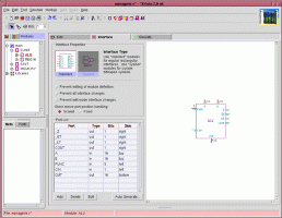
If you have the top-level module selected, the interface editor will
display a graphical representation for the interfaces of all modules
loaded in your design as shown in Figure 3.12.
You can edit the interfaces directly on this page, or you can double
click on a module, either its graphical form or its name in the module
list, to open the single-module interface editor.
There are two basic types of module interfaces: standard interfaces,
and symbol interfaces. A standard interface is a rectangular box with
ports on the edges of the box. A symbol interface is an arbitrary
user-defined symbol created through a bitmap editor. Most of the
time, you will likely use standard interfaces, but if you wish to
create your own gates, you can create your own symbols for them.
3.6.1 Standard Module Interfaces
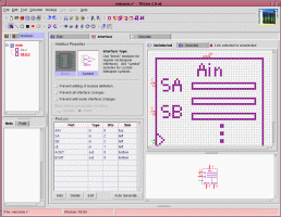
Figure 3.13 shows the single-module
interface editor for a module with a standard interface. At the top
of the "Interface Properties" box, is a selector that lets you choose
between the "Standard" and "Symbol" interface types. While the module
is open, you can switch back and forth between the two types without
losing any work you have done on either interface. Below the
interface type selector, are the module properties. These are the
same properties that can be specified through the module creation and module properties dialog boxes.
Editing Through The Port List
Below the "Interface Properties" box, is the "Port List". The Port
List lists all of the ports on the module. For each port, the list
includes the name of the port, the type (input, output, or inout), the
bit width, and the side of the module box on which the port it
attached. To change a value, double click on it. For the port name,
you can enter a new port name. Names that begin with a '_' will be
displayed with an over-bar to indicate that they are active low
signals. For the other fields, a drop down selector will appear
allowing you to change the value. Click anywhere outside the open
value to close it and make the change effective. Your changes will be
reflected in the graphical view of interface. You can also hit the
tab key to advance and enter a value for the next field.
To add a new port, you can either double click on the next empty line
in the port list, or press the "Add" button. TkGate will attempt to
guess an appropriate name for the new port, but you can type in your
own name if you prefer. To delete a port, select it and press the
"Delete" button.
You can reorder the ports by selecting and dragging them up or down in
the port list. Ports that are on the same "Side" will be arranged in
the same in both the port list and in the graphical representation of
the interface.
Graphical Editing
You can also edit the interface graphically. To change the size of
the box, grab a corner or side with the mouse and drag in it or out.
To edit the properties of a port, double click on its name in the
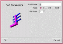
graphical representation of the interface. The Port Parameters dialog
box shown in Figure 3.14 will appear
allowing you to change the name, type and bit size of the port. The
new values will be updated in the port list after you click "OK".
To add a new port, right click on the edge of the rectangle at the
point you wish to add the port and select "Add Input..", "Add
Output.." or "Add InOut..". The Port Parameters dialog box will
appear in this instance too allowing you to enter the port name and
bit size. To delete a port, use the
tool and "cut" the wire off the edge of the
interface.
To reposition ports, grab them and slide them back and forth on the
edge to which they are attached. However, to change the edge to which
they are attached, you will need to change the "Side" in the port
list.
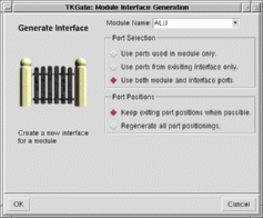
3.6.2 Automatic Interface Generation
Rather than manual edit the interface of a module, you can
automatically generate an interface after you have completed the
internal definition of a module. To do this, open the module in the
interface editor and press the "Auto Generate..." button. This will
bring up the Interface Generator dialog box shown in Figure 3.15. Select the module for
which you wish to create an interface, then choose "Port Selection"
and "Port Positions" options.
The port selection option tells the interface generator which ports
should be included on the generated interface. The possible options are:
- Use ports used in module only: Only ports that are used in
the definition of the module will result in ports on the interface.
If you have not created the internal definition yet, then no ports
will be generated.
- Use ports from existing interface only: Only ports that are
used on the current interface will be used. This option can be used
when you want to regenerate the positions of the ports.
- Use both module and interface ports: Ports that are used
either in the definition, or in the current interface will be
generated on the new interface.
The port position option tells the interface generator how the ports
on the new interface should be positioned. The possible options are:
- Keep existing port position when possible: If regenerating
an interface, the positions of ports that have already been positioned
will not be modified. Only new ports will be positioned.
- Regenerate all port positions: Existing positions of any
ports on the current interface will be ignored, and a new interface
will be generated from scratch.
3.6.3 Symbolic Module Interfaces
You can use the built-in bitmap editor to design your own symbols for
modules that you create. Open the module in the interface editor and
select "Symbol" for the interface type. The symbol editor includes a
bit map editor on the top, and a view of your device on the bottom.
You can edit the ports in the port list in the same way as for
standard modules. Drag the name of any newly created ports onto the
bit-map editor to allow you to position it.
You must create an "Unselected" and a "Selected" version of your
symbol. The "Unselected" version is the appearance when the symbol is
not selected, and the "Selected" version is the appearance when you
have selected it in the editor. Normally you can just draw the
"Unselected" version, copy and paste it into the "Unselected" version,
then press the
button on
the toolbar to automatically boldify your symbol. However, you may
want to use the editor to do some final touch-ups.
There are six symbol editor tools that you can use in designing your
symbol:
Tool | Description |
|
 |
Bit Tool - Click the left mouse button to set a bit, and
the right mouse button to clear a bit. You can also press and hold
the mouse button to set/clear multiple bits and you move the mouse.
|
 |
Line Tool - Click and hold the left mouse button to set one end
of the line, and drag the mouse to the other end and release to draw a
line. The same action with the right mouse button will clear a line.
|
 |
Rectangle Tool - Click and hold the left mouse button to set
one corner of the rectangle, and drag the mouse to the other corner
and release to draw a rectangle. The same action with the right mouse
button will clear the rectangle.
|
 |
Filled Rectangle Tool - Click and hold the left mouse button to
set one corner of the filled rectangle, and drag the mouse to the
other corner and release to draw a filled rectangle. The same action
with the right mouse button will clear the filled rectangle.
|
 |
Port Tool - Use this tool to select and manipulate ports.
Click and drag the port to move it. Use the and buttons to rotate the port clockwise or
counter-clockwise.
|
 |
Area Select Tool - This tool allows you to select a rectangular
area, then use the cut, copy and paste tools. There are two types of
paste operations. A normal paste overwrites all bits with the contents of the
cut buffer. The overlay paste , pastes only the bits that are set in the
cut buffer, combining the cut buffer with the existing image. The
selection also limits the scope of the bit shifting and rotating
operations to the selection.
|
|
You can also use the
and
buttons to rotate the
image clockwise or counter-clockwise, or the shift buttons such as
to shift the bits left, right,
up or down. You can use the area selection tool
to limit the scope of these operations to
the selected area.